|
||||||||||||||||||||||||||||||||||||||||||
|
Improving the quality of multi-generation imagesJohn Strait
Some loss of sharpness is an unavoidable result of resampling an image when the sampling locations are not on pixel centers. When an image processing task has multiple steps, it is most natural to perform these steps sequentially with each step reading from the result of the previous step. Each subsequent image generation decreases the sharpness of the final result. The more generations, the more degraded the resulting image becomes. Better resampling methods can help to control this image degradation. In his excellent paper Testing Interpolator Quality [1], Prof. Helmut Dersch discusses the effects of repeated interpolation and shows how image quality is improved by the use of better interpolation algorithm. If it were possible to collapse multiple generations of image resampling into a single image resampling step, the quality of the interpolation algorithm would be much less significant. This paper describes a technique provided by The Panorama Factory for improving image quality by recalculating the final image in a single resampling generation. Prof. Dersch tests interpolator quality by repeatedly rotating an image by 5 degree steps until the image is rotated 180 degrees in a total of 36 generations. A final (lossless) 180 degree rotation restores the image to its original orientation. We can judge the quality of an interpolation method by comparing the final image to the original and by comparing final images produced by different interpolators. Figures 1, 2 and 3 illustrate The Panorama Factory method with the images used by Prof. Dersch. Figure 4 illustrates The Panorama Factory method with a portion of a stitched panorama. Figures 1a and 2a are © 1999 by Helmut Dersch. Figure 3a, a Zone Plate [3, 4], is © 1999 by Ken Turkowski [5]. Figure 4 is © 1999 by John Strait. Unauthorized reproduction is a violation of copyrights. The released version of The Panorama Factory does not include an image rotation command per se. It is possible, however, to rotate an image using the Crop command. The images used in this article were rotated with an unreleased image rotation extension that permits rotation of images by specific angles. This extension will be available in a future release of The Panorama Factory. The Panorama Factory uses the common bi-linear interpolation method. Figure 1b shows the effect of 36 image generations using bi-linear interpolation. This begs the question: why rotate the image by 36 5-degree steps when a single 180 rotation achieves the same result? It is easy to collapse multiple rotations into a single rotation by adding the rotation angles. It is somewhat more difficult to combine different types of transformations.
When creating a stitched panoramic image from conventional photographs, for example, there may be as many as 4 independent image generations of three different types. In a typical panoramic image created from scanned negatives, The Panorama Factory applies the following transformations in sequence:
These four operations combine linear and non-linear image transformations of three different types. It is very difficult to compose these into a single image transformation. The remainder of this article explains how The Panorama Factory solves this problem and illustrates the effectiveness of its technique. Many image processing applications use an imperative model. That is, the user sequentially performs functions on an original image. After each image processing operation, the output of the operation replaces the input image. In contrast, The Panorama Factory uses a project model. As the user performs image processing functions, The Panorama Factory builds a project file describing their sequence and their parameters. In the terminology of The Panorama Factory, the project file contains recipes for creating each subsequent image from its respective input image(s). If the user retains the original input images, the final images can be recreated from the recipes. Intermediate images need not be retained. Collapsing multiple generations into a single step In normal operation, The Panorama Factory computes images by resampling their immediate
predecessor images. For example, when you The Panorama Factory project organization enables it to collapse all image processing generation into a single step. From the user's point of view, the project file contains recipes that transform whole input images into output images. For example, an image rotation function might be representated from the user's point of view in this way:
Internally, however, each recipe can be understood as a function that computes the location in the input image for a given location in the output image:
For example, if fi represents a rotation by the angle a :
The Panorama Factory applies fi for each output pixel location, using interpolation to sample the input image at the indicated location. If each image processing step can be described in this way, we can compose all of the functions together. In this way, we can generate the final output image Imagen by directly sampling the original input image Image0:
The Panorama Factory's Improve quality command recreates the current image by tracking each pixel back to its corresponding location within the original imported images as described in the earlier section. This improves the image quality by replacing multiple image generations with a single generation. Figures 1c, 2c and 3c show the results of calculating images with a single resampling step in The Panorama Factory.
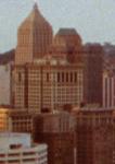
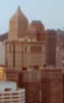
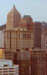
The center of rotation is neither on a pixel center nor at the junction of 4 pixels because of the very indirect way the rotations were constructed (see Images used in this article). This asymmetry produces the asymmetric aliasing artifacts that appear in Figure 3c. You may wonder how significant this technique is in practice. Figure 4 shows excerpts from an actual Panorama Factory project. Figure 4a shows a portion of an original imported image. Figure 4b shows the corresponding portion of the resulting panoramic image in an overlap region. This portion of the panoramic image has undergone all four image transformations as described in the statement of the problem. Figure 4c shows the result recalculated in a single generation using The Panorama Factory's Improve quality command. These images illustrate the effectiveness of this technique.
Panoramic stitching applications must perform a sequence of image processing steps to create cylindrical or spherical panoramic images from sets of planar images. Each subsequent image transformation contributes to the degrading of the final image quality. The Panorama Factory includes a technique for eliminating all but a single image generation. This technique maximizes image quality at the expense of a small delay in processing time. Unlike some other panoramic stitching applications, The Panorama Factory includes commands for trimming and rotating the original images, for correcting non-linear distortions introduced by imperfect camera lenses and for rotation of the final output image. Other applications require the user to perform additional image processing functions outside of the stitching application. By including these functions in The Panorama Factory's project model, the user can achieve a better final result through use of the Improve quality command.
|
|||||||||||||||||||||||||||||||||||||||||
|
Revised: April 28, 2004 © 1999-2005 Smoky City Design, LLC and John Strait |
||||||||||||||||||||||||||||||||||||||||||